Quantum code is not like classical code
Debugging quantum code is different from fixing classical software because quantum computers are probabilistic. Qubits aren't just 1s and 0s; they exist in superpositions. This means errors aren't always a simple 'wrong' answer, but a shift in the probability of getting the right one. This inherent uncertainty makes errors less about definitive "right’ or ‘wrong" answers and more about deviations from expected probabilities.
This probabilistic behavior is further complicated by the fragility of quantum states. The act of observing a quantum state – which is often necessary for debugging – inevitably disturbs it. This is a consequence of the quantum measurement process, and it means that traditional debugging techniques like breakpoints and step-through execution are often ineffective or misleading. Trying to pinpoint the exact moment an error occurred can alter the system’s state before you can observe it.
The implications are significant. Errors in quantum programs don’t always manifest as crashes or incorrect outputs in the same way they do in classical code. Instead, you might see subtly altered probabilities, reduced fidelity, or unexpected correlations. This requires a shift in mindset and the adoption of new debugging strategies tailored to the unique characteristics of quantum systems. Expect to spend more time analyzing statistical results than tracing individual code lines.
Qiskit error mitigation
Qiskit has tools to handle noise. These don't fix the hardware, but they help clean up the results. Zero-noise extrapolation (ZNE) is the most common method. You run the same circuit at different noise levels and calculate what the result would be if the noise weren't there. It involves running the same quantum circuit at different levels of noise, then extrapolating the results back to the zero-noise limit.
Probabilistic error cancellation (PEC) is another important approach. PEC attempts to learn the error characteristics of the quantum hardware and then apply corrections to the measurement outcomes. Effectively, it creates a model of the noise and tries to undo its effects. Qiskit’s `mitigation` module provides classes and functions to implement these techniques, and the documentation is regularly updated with best practices and new features.
When to use each technique depends on the nature of the errors and the specific circuit. ZNE is often effective for errors that scale linearly with the circuit depth. PEC can be more effective for complex error models. Consider using both in combination for optimal results. The Qiskit documentation provides detailed examples and tutorials on how to apply these error mitigation strategies to your quantum programs.
Recent updates to Qiskit have focused on automating the error mitigation process and improving the accuracy of the extrapolation and cancellation algorithms. Experiment with the latest versions of the `mitigation` module to take advantage of these improvements. Be prepared to tune the parameters of these techniques to achieve the best performance for your specific hardware and application.
Cirq’s Simulator and Error Models
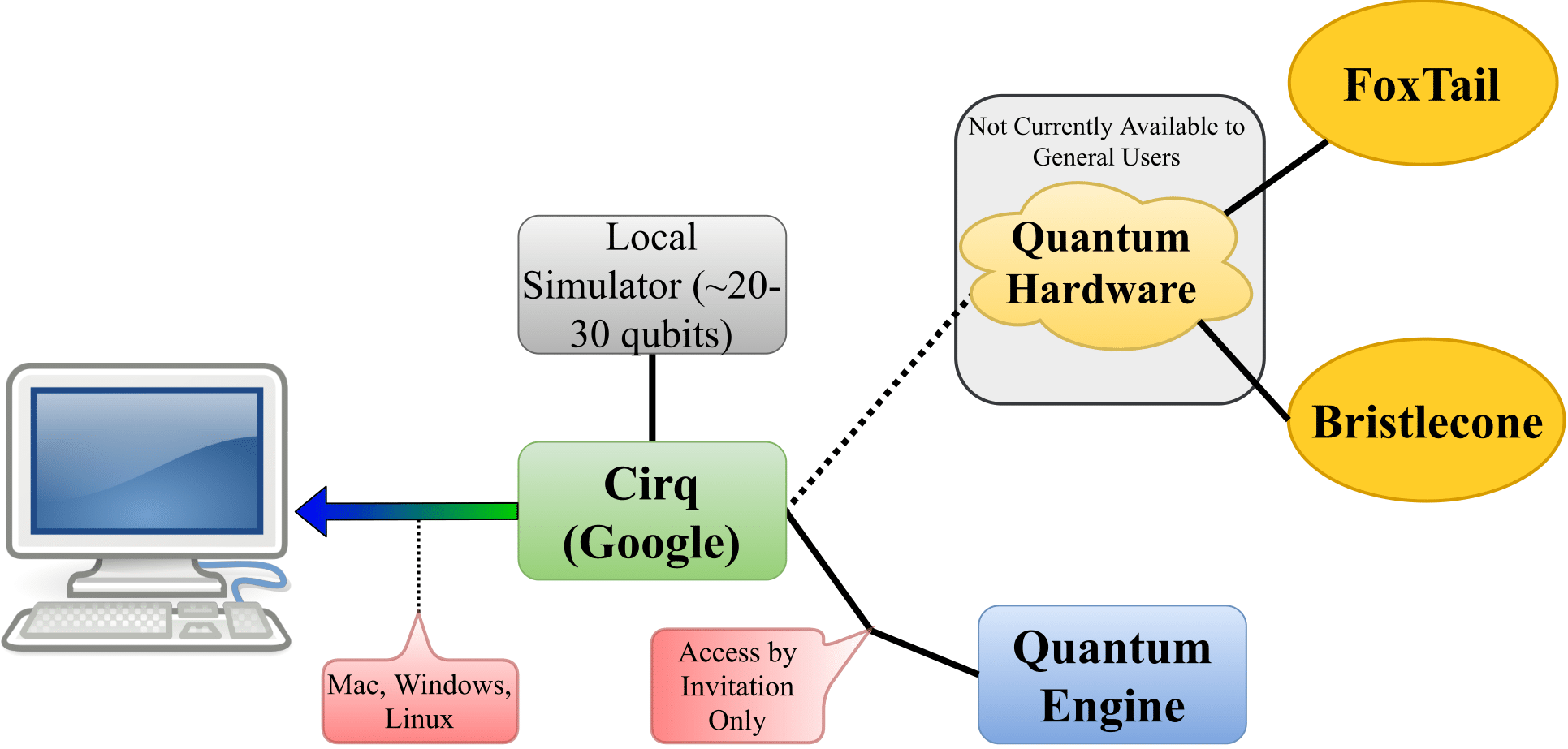
Google’s Cirq framework offers robust simulation capabilities, crucial for quantum computing debugging. Cirq’s simulator allows you to reproduce errors that occur on real quantum hardware, helping you isolate and understand the root causes of problems. You can run your circuits in a controlled environment, stepping through the computation and inspecting the state of the qubits at each gate.
A key feature of Cirq is the ability to define custom error models. These models allow you to simulate realistic noise conditions, such as decoherence, gate errors, and measurement errors. By carefully crafting the error model, you can test your code against a variety of noise scenarios and assess its robustness. This is particularly important when targeting specific quantum hardware platforms.
Choosing the right error model is critical. It should accurately reflect the characteristics of the target hardware. Cirq provides several built-in error models, but you may need to create your own to capture the specific noise profile of your device. The documentation outlines how to define custom error models using Cirq’s flexible API.
Recent improvements to Cirq’s simulator have focused on increasing its speed and scalability, allowing you to simulate larger and more complex quantum circuits. This makes it easier to debug and optimize your code for real-world applications.
Reading Qiskit exception messages
Quantum errors often surface as opaque exception messages. Many newcomers to Qiskit struggle to decipher these errors and understand their underlying causes. A common error is `QiskitError: Circuit construction error`. This usually indicates a problem with the way you’ve defined your quantum circuit – perhaps an invalid gate, an incorrect qubit connection, or a logical inconsistency.
Another frequent error is `BackendError: Job submission failed`. This can stem from several issues, including exceeding the qubit limit of the backend, using an unsupported gate, or encountering a temporary hardware issue. Carefully check the backend specifications and your circuit’s requirements to resolve this. `QiskitError: Result retrieval failed` often points to a problem with the job status or network connectivity.
When troubleshooting, always start by examining the full error message, including the traceback. This provides valuable clues about the location and nature of the error. Consult the Qiskit documentation and online forums for similar error messages and potential solutions. Don't hesitate to simplify your circuit to isolate the problem.
Cirq’s Visualization Tools for Debugging
Cirq provides powerful visualization tools that can significantly aid in debugging. These tools allow you to inspect the structure of your quantum circuit, visualize gate timings, and examine qubit connectivity. Visualizing the circuit diagram can help you identify potential errors in your design, such as unnecessary gates or inefficient qubit routing.
Gate timings are crucial for accurate quantum computation. Cirq’s visualization tools allow you to inspect the timing of each gate, ensuring that they are executed in the correct order and with the appropriate delays. This can help you identify potential sources of error related to gate crosstalk or timing conflicts. I think this is a particularly underutilized feature.
Qubit connectivity is another important factor. Cirq’s visualizations show you which qubits are directly connected, allowing you to optimize your circuit for the specific hardware topology. Poor qubit placement can lead to increased gate errors and reduced fidelity. By carefully considering qubit connectivity, you can minimize these errors and improve the performance of your quantum program.
Community Insights: Common Quantum Bugs
Based on observations from forums and discussions, several common quantum programming errors consistently arise. Circuit construction errors, such as incorrect qubit assignments or invalid gate sequences, are frequent. These often stem from a misunderstanding of the underlying quantum mechanics or the specific syntax of the chosen framework.
Measurement errors are another common issue. These can be caused by inaccurate calibration of the measurement devices, noise in the measurement process, or incorrect handling of measurement outcomes. State preparation errors, where the initial quantum state is not correctly prepared, can also lead to significant errors.
Many developers struggle with qubit connectivity limitations. Attempting to apply gates between non-connected qubits can result in errors or unexpected behavior. Careful circuit design and qubit routing are essential to avoid these issues. A common tip is to use SWAP gates strategically to move qubits into a connected configuration, but be mindful of the added gate count.
Another frequently reported problem involves handling complex quantum algorithms. Ensuring proper entanglement and interference patterns requires a deep understanding of the algorithm's logic and the limitations of the hardware. Thorough testing and validation are crucial to ensure the correctness of your implementation.
- Circuit errors like assigning gates to the wrong qubits or using invalid sequences.
- Measurement Errors: Inaccurate calibration, noise in the measurement process.
- State Preparation Errors: Incorrect initial quantum state.
- Qubit Connectivity Issues: Attempting gates between non-connected qubits.


No comments yet. Be the first to share your thoughts!